Hello, dear readers and guests of the "Notes of an Electrician" website.
The other day I was replacing the old chandelier with a new five-arm one.
The house was a panel house, so I want to pay special attention to this, because there is a small nuance that I encountered again. But first things first.
First you need to take care of your personal electrical safety. We turn it off into the necessary circuit breaker, on the supply wires near the chandelier or single-pole indicator, and only after that we start working.
You will say that to do this kind of work, it is enough to turn off both keys of the switch. I answer, what if some one initially connected it incorrectly and the switch does not switch phases, but zeros? Moreover, according to the customer, the two-button switch was faulty. But I'll talk about this at the end of the article.
![]()

We bite off the wires and remove the old chandelier. The photo shows that there is one on the supply wires, but on the wires going directly to the chandelier: two yellow wires are phases from different switch keys, and the blue wire is zero. Now we will not remember the marking, because it will still need to be rechecked.

To install the mounting plate for a new chandelier, you need to dismantle the decorative cover and the hook. We gouge it slightly, it falls out together with the holder hook (by the way, it is also plastic).
And here we have such a view on the ceiling (at the beginning of the article I talked about the nuance). This is not the first panel house where I come across such "technological" holes. When installing a new chandelier, it is imperative to hide this horror. 
But there is a problem here. It consists in the fact that if you drill holes for the fastening plate from the edge of the plate, then it (the edge) may break off (crumble) when drilling with a hammer drill. So I had to shift the installation of the chandelier a little in order to drill holes not on the edge of the plate, but a little further. In this case, it must be borne in mind that the base of the chandelier completely covers this hole. If you cannot completely close it, then you can carefully plaster it.


Dealing with the wires coming out of the ceiling
Electrical wiring in panel houses is laid, either in special channels (voids), or in the joints between the plates. Most often, there are channels in the ceiling slab (floor slab) that run parallel to each other at a certain distance. In my case, the wires lie directly on the surface of the ceiling slab. It all depends on the series of panel houses.
The electrical wiring is aluminum and is made with a three-core wire APPV (3x2.5).
And now we need to deal with the wires coming out of the ceiling, namely, find two phase (L1, L2) and one zero (N). This can be done in several ways. I'll show you the simplest one.
Make sure that the bare ends of the wires do not touch each other, to do this, carefully spread them apart.
- phase from the first switch key (L1)
- phase from the second pushbutton of the switch (L2)
- zero (N)

We turn on the disconnected circuit breaker in the apartment or floor panel. Then we turn on the first button of the switch and using the single-pole indicator or voltage indicator "Contact-55EM" we find the phase (L1), which is connected to the first button of the switch. You can find out how to use these devices by following these links:
Then turn off the first key and turn on the second. Similarly, we are looking for the phase (L2), which is connected to the second key.
Do not forget to first make sure that your pointer is in good working order by checking it on live parts that are known to be energized.
Thus, we have found two phases - L1 and L2. We still have the third wire - this is zero N.
How to connect a chandelier through a two-button switch
Here is the wiring diagram for a chandelier consisting of five lamps.
- phase L1 (orange)
- phase L2 (yellow)
- zero N (blue)

Dealing with chandelier wires
First of all, we need to figure out the diagram of the chandelier itself, i.e. those wires that come out of its base.
In my example, each chandelier light bulb has its own wires coming out. In total, 10 wires are removed from the base of the chandelier: 5 phase (brown) and 5 zero (blue). This can be clearly seen in the photo below.

The advantage of such a chandelier is that a combination of light bulbs can be made at will, for example, only one light bulb can be connected to the first group, and the rest of the lamps to the second group.
We agreed with the customer that the first group of lamps will include two bulbs, and the second group - the other three.
I will make all wire connections using two and three wires. By the way, a new 221 series was recently released - it is more convenient and compact.

So, we take two brown wires, preferably not near the lamps, and connect them together. This will be our first twist and we will name it - L1. Then we take the three remaining brown wires and we also twist them together. This will be the second twist, which we will designate - L2. Here's what you should get.

Insert the first (L1) and second (L2) twists into the corresponding Vago terminals.

We twist five blue wires together in any order (2 + 3) and connect to the three-wire Vago terminal. This will be the zero terminal (N).

It turned out the following.


It remains to connect the supply wires to the Vago terminals in accordance with the accepted marking.

You will now say that the Wago 222 series is designed to connect only copper wires. I know, but I deliberately use them for connections and aluminum wires due to the fact that the current carrying bar of the terminal is tinned, not copper. This means that there is no direct aluminum-copper contact.
Well, I like the terminals of this series.
The only thing is that they do not contain a paste based on quartz with technical petroleum jelly, which would protect the compound from oxidation, destroying the formed oxide film in aluminum. But this is not a problem, you can purchase Wago Alu-Plus paste separately and inject it directly into the terminal block.

We carefully lay the wires at the base of the chandelier (there is not much space there) and install it on the bracket. We tighten the decorative nuts. The chandelier is installed.

We insert 25 (W) lamps of warm white color with an E14 base into the CFL chandelier.

At the beginning of the article, I said that the customer had a faulty two-button switch. In his words, "with a light touch of the switch, he turned on and off the lamps several times in a row."

I took off the old switch and the reason for its malfunction was obvious.

The latch of fastening to the switch body has broken off at the contact switch. In the photo below - a broken latch on the left, on the right - a whole one.

The switch was removed in the place with the cover, but must be removed separately.

This malfunction was the result of the "chaotic" operation of the two-button switch. The switch was not attached (fixed) to the case on the right side, the pressure on the contacts was weakened, and sometimes it was not there at all. When the right key was turned on, the movable part of the contact was not pressed against the fixed part - the contact disappeared and burned out.

Instead of the old switch, I installed a new one with a ceramic base from Powerman (China).
Something recently, I have often come across this brand, well, for example, recently, and it was the same "Powerman".


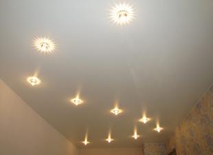
Now you can check the work of the new chandelier. Works properly!

P.S. I hope that after reading this article, you will not have any questions about how to connect a chandelier with a two-button switch. Well, if they do arise, then feel free to ask through the comment form or feedback. Thank you for the attention.